Note
Go to the end to download the full example code.
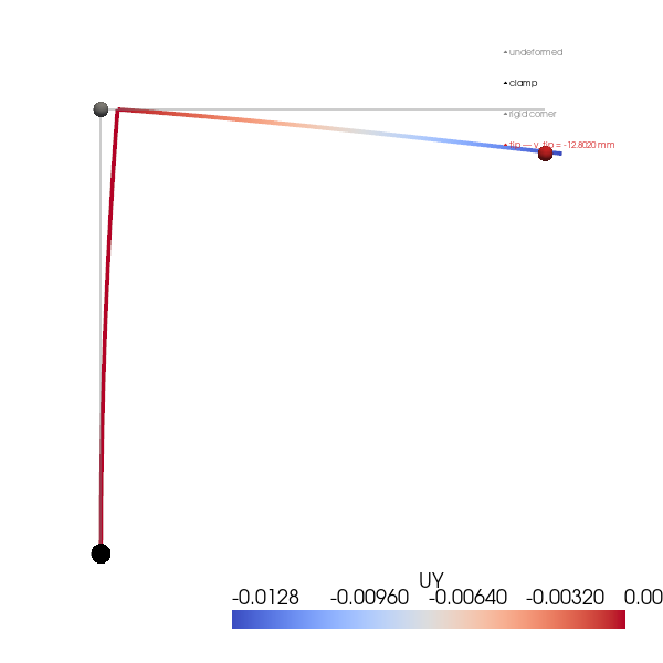
L-shaped frame under tip load — Castigliano on a two-member portal#
Two prismatic Bernoulli beams welded at a rigid corner form an L-shaped portal frame. A vertical column of length \(L_{v}\) runs from the clamp at the origin to the corner; a horizontal beam of length \(L_{h}\) cantilevers from the corner. A concentrated transverse load \(P\) acts at the free tip \((L_{h}, L_{v})\) in the \(-y\) direction (downward).
Reading off the moments by superposition:
Column (vertical, \(0 \le y \le L_{v}\)): axial force \(N = -P\) (compression); the tip load applied at horizontal offset \(L_{h}\) produces a constant moment about \(z\),
\[M_{\mathrm{col}}(y) \;=\; -\, P\, L_{h}.\]Horizontal beam (\(0 \le x \le L_{h}\)): standard cantilever-with-tip-load moment,
\[M_{\mathrm{beam}}(x) \;=\; -\, P\, (L_{h} - x).\]
Castigliano’s theorem gives the tip deflection in the load direction (Timoshenko & Young 1968 §80; Roark Table 9 case 6):
with the axial-strain term \(P L_{v} / (E A)\) from the column. For a slender frame \((I / A \ll L^{2})\) the axial contribution is negligible — at the default geometry below it sits 6 000× below the bending term.
Two limits collapse the formula:
\(L_{v} \to 0\) — the column vanishes and the structure reduces to a horizontal cantilever: \(\delta = P L_{h}^{3} / (3 E I)\). Recovers the Cantilever tip deflection — Euler-Bernoulli closed form result.
\(L_{h} \to 0\) — only axial compression of the column survives: \(\delta = P L_{v} / (E A)\). Recovers the Single-hex uniaxial tension — Hooke’s law + Poisson check / Hooke’s-law axial response.
Implementation#
40-element BEAM2 (Hermite-cubic Bernoulli) line for the column, 40 more for the horizontal beam — sharing a common node at the rigid corner so all moment / shear / axial transfer is implicit. The clamp at \((0, 0, 0)\) pins all six DOFs; out-of-plane DOFs are pinned across the line so the response stays strictly 2D in the \(x\)-\(y\) plane.
References#
Timoshenko, S. P. and Young, D. H. (1968) Elements of Strength of Materials, 5th ed., Van Nostrand, §80 (Castigliano on a curved-beam / frame).
Roark, R. J. and Young, W. C. (1989) Roark’s Formulas for Stress and Strain, 6th ed., McGraw-Hill, Table 9 case 6 (right-angle bend, end load).
Cook, R. D., Malkus, D. S., Plesha, M. E., Witt, R. J. (2002) Concepts and Applications of Finite Element Analysis, 4th ed., Wiley, §16.5 (multi-element frame assembly).
from __future__ import annotations

import numpy as np
import pyvista as pv

import femorph_solver
from femorph_solver import ELEMENTS
Problem data — equal-leg L-frame#
E = 2.0e11
NU = 0.30
RHO = 7850.0
WIDTH = 0.05
HEIGHT = 0.05
A_section = WIDTH * HEIGHT
I_z = WIDTH * HEIGHT**3 / 12.0
I_y = HEIGHT * WIDTH**3 / 12.0
J = (1.0 / 3.0) * min(WIDTH, HEIGHT) ** 3 * max(WIDTH, HEIGHT)

L_v = 1.0  # column length [m]
L_h = 1.0  # beam length [m]
P = 1.0e3  # tip load [N, downward = -y]

EI = E * I_z

# Closed-form tip deflection (Castigliano, Roark Table 9 case 6).
delta_bending = P * L_h**2 * L_v / EI + P * L_h**3 / (3.0 * EI)
delta_axial = P * L_v / (E * A_section)
delta_tip_pub = -(delta_bending + delta_axial)  # downward in -y

print("L-shaped frame under tip load")
print(f"  column L_v = {L_v} m, beam L_h = {L_h} m, P = {P} N (-y)")
print(f"  E = {E:.2e} Pa, I = {I_z:.3e} m^4, A = {A_section:.3e} m^2")
print()
print("Closed-form references (Castigliano / Roark Table 9 case 6):")
print(f"  bending δ           = {-delta_bending * 1e3:+.4e} mm")
print("    = P L_h² L_v / E I + P L_h³ / (3 E I)")
print(f"  axial δ (column)    = {-delta_axial * 1e3:+.4e} mm   (= P L_v / E A)")
print(f"  total δ_tip         = {delta_tip_pub * 1e3:+.4e} mm")
print(
    f"  axial / bending ratio = {delta_axial / delta_bending:.2e}  "
    "(slender-frame regime — axial negligible)"
)
L-shaped frame under tip load
  column L_v = 1.0 m, beam L_h = 1.0 m, P = 1000.0 N (-y)
  E = 2.00e+11 Pa, I = 5.208e-07 m^4, A = 2.500e-03 m^2

Closed-form references (Castigliano / Roark Table 9 case 6):
  bending δ           = -1.2800e+01 mm
    = P L_h² L_v / E I + P L_h³ / (3 E I)
  axial δ (column)    = -2.0000e-03 mm   (= P L_v / E A)
  total δ_tip         = -1.2802e+01 mm
  axial / bending ratio = 1.56e-04  (slender-frame regime — axial negligible)
Build the two-segment BEAM2 frame#
N_PER_SEG = 40

# Column: 0 → L_v along +y axis.
col_y = np.linspace(0.0, L_v, N_PER_SEG + 1)
col_pts = np.column_stack((np.zeros_like(col_y), col_y, np.zeros_like(col_y)))

# Beam: 0 → L_h along +x axis at y = L_v.  Skip the corner node (it's
# already in the column) and concatenate the rest.
beam_x = np.linspace(0.0, L_h, N_PER_SEG + 1)[1:]
beam_pts = np.column_stack((beam_x, np.full_like(beam_x, L_v), np.zeros_like(beam_x)))

pts = np.vstack((col_pts, beam_pts))

# Cells — column elements then beam elements.  Both segments share
# node ``N_PER_SEG`` (the corner), so beam-element indices have an
# implicit offset of ``N_PER_SEG`` for their first node.
cells = []
for i in range(N_PER_SEG):
    cells.append([2, i, i + 1])
# Beam segment: connect corner (node N_PER_SEG) to first beam point
# (which is the point right after corner = N_PER_SEG + 1).
cells.append([2, N_PER_SEG, N_PER_SEG + 1])
for i in range(1, N_PER_SEG):
    cells.append([2, N_PER_SEG + i, N_PER_SEG + i + 1])
cells_arr = np.array(cells, dtype=np.int64)

n_cells = cells_arr.shape[0]
grid = pv.UnstructuredGrid(
    cells_arr.ravel(),
    np.full(n_cells, 3, dtype=np.int64),
    pts,
)

m = femorph_solver.Model.from_grid(grid)
m.assign(
    ELEMENTS.BEAM2,
    material={"EX": E, "PRXY": NU, "DENS": RHO},
    real=(A_section, I_z, I_y, J),
)

n_nodes = pts.shape[0]
print(f"\nL-frame mesh: {n_nodes} nodes, {n_cells} BEAM2 cells")
L-frame mesh: 81 nodes, 80 BEAM2 cells
Boundary conditions#
Clamp at (0, 0, 0) — node 1. Out-of-plane motion suppressed at every node so the response stays strictly 2D in x-y.
Tip load at (L_h, L_v, 0)#
Solve + extract tip deflection#
res = m.solve_static()
dof_map = m.dof_map()
disp = np.asarray(res.displacement, dtype=np.float64)


def _node_dof(node_id: int, dof_idx: int) -> float:
    """0=UX, 1=UY, 2=UZ, 3=ROTX, 4=ROTY, 5=ROTZ."""
    rows = np.where(dof_map[:, 0] == node_id)[0]
    for r in rows:
        if int(dof_map[r, 1]) == dof_idx:
            return float(disp[r])
    return 0.0


v_tip_fe = _node_dof(int(i_tip + 1), 1)
err = (abs(v_tip_fe) - abs(delta_tip_pub)) / abs(delta_tip_pub) * 100.0

print()
print(f"{'quantity':<22}  {'FE':>14}  {'published':>14}  {'err':>9}")
print(f"{'-' * 22:<22}  {'-' * 14:>14}  {'-' * 14:>14}  {'-' * 9:>9}")
print(
    f"{'v_tip (UY)':<22}  {v_tip_fe * 1e3:>10.4f} mm  "
    f"{delta_tip_pub * 1e3:>10.4f} mm  {err:>+8.4f}%"
)

assert abs(err) < 0.1, f"v_tip deviation {err:.4f} % exceeds 0.1 %"
quantity                            FE       published        err
----------------------  --------------  --------------  ---------
v_tip (UY)                -12.8020 mm    -12.8020 mm   -0.0000%
Render the deformed frame#
g = m.grid.copy()
disp_xyz = np.zeros((g.n_points, 3))
for ni in range(g.n_points):
    disp_xyz[ni, 0] = _node_dof(int(ni + 1), 0)
    disp_xyz[ni, 1] = _node_dof(int(ni + 1), 1)
g.point_data["displacement"] = disp_xyz
g.point_data["UY"] = disp_xyz[:, 1]

scale = 1.0 / max(abs(v_tip_fe), 1e-12) * 0.1
warped = g.copy()
warped.points = np.asarray(g.points) + scale * disp_xyz

plotter = pv.Plotter(off_screen=True, window_size=(600, 600))
plotter.add_mesh(g, color="grey", opacity=0.4, line_width=2, label="undeformed")
plotter.add_mesh(warped, scalars="UY", cmap="coolwarm", line_width=4)
plotter.add_points(
    np.array([[0.0, 0.0, 0.0]]),
    render_points_as_spheres=True,
    point_size=18,
    color="black",
    label="clamp",
)
plotter.add_points(
    np.array([[0.0, L_v, 0.0]]),
    render_points_as_spheres=True,
    point_size=14,
    color="#888888",
    label="rigid corner",
)
plotter.add_points(
    np.array([[L_h, L_v + scale * v_tip_fe, 0.0]]),
    render_points_as_spheres=True,
    point_size=14,
    color="#d62728",
    label=f"tip — v_tip = {v_tip_fe * 1e3:.4f} mm",
)
plotter.view_xy()
plotter.add_legend()
plotter.show()
Take-aways#
print()
print("Take-aways:")
print(f"  • v_tip within {abs(err):.4f} % of P L_h² L_v / E I + P L_h³ / (3 E I) + P L_v / (E A).")
print(
    "  • Bending dominates the slender-frame response; the column's axial "
    f"compression contributes only {abs(delta_axial / delta_bending) * 100:.4f} % "
    "of the tip deflection at this geometry."
)
print(
    "  • Limit cases collapse cleanly: L_v → 0 ⇒ horizontal cantilever P L³/(3 E I); "
    "L_h → 0 ⇒ axial column P L / (E A)."
)
Take-aways:
  • v_tip within 0.0000 % of P L_h² L_v / E I + P L_h³ / (3 E I) + P L_v / (E A).
  • Bending dominates the slender-frame response; the column's axial compression contributes only 0.0156 % of the tip deflection at this geometry.
  • Limit cases collapse cleanly: L_v → 0 ⇒ horizontal cantilever P L³/(3 E I); L_h → 0 ⇒ axial column P L / (E A).
Total running time of the script: (0 minutes 0.185 seconds)