Note
Go to the end to download the full example code.
Cantilever under linearly-varying distributed load (triangular)#
A clamped-free prismatic beam of length \(L\) carrying a triangular distributed load that grows from zero at the root to peak intensity \(q_{0}\) at the tip:
The total downward load is \(Q = q_{0}\, L / 2\) with centroid at \(x = 2 L / 3\). Integrating shear and moment,
so the moment at the root takes its closed-form value
Tip deflection by virtual work (unit-load applied at the tip, \(m(x) = -(L - x)\)):
(Timoshenko 1955 §32; Roark Table 8 case 5 — load distribution peaking at the free end). Tip slope (\(\theta_{\mathrm{tip}} = q_{0}\, L^{3} / (8\, E\, I)\)) and the deflection at any interior point follow by the same integration.
Comparison to a uniform load: if instead the same total load \(Q = q_{0} L / 2\) is spread uniformly (\(\bar w = q_{0}/2\)), the tip deflection is
so \(\delta_{\mathrm{tip}}^{\mathrm{UDL}} / \delta_{\mathrm{tip}}^{\mathrm{tri}} = 120 / (16 \cdot 11) = 15/22 \approx 0.682\). Concentrating the load toward the tip deflects the beam ~46 % more than spreading it uniformly, even though the total load is identical — the moment-arm distribution dominates.
Implementation#
A 40-element BEAM2 (Hermite-cubic Bernoulli) line spans the beam. The triangular load is converted to consistent nodal forces by trapezoidal integration of \(w(x)\) over each element edge (interior nodes receive \(w(x_i)\, h\), the end nodes \(w(x_i)\, h / 2\)); the small nodal-discretisation error this introduces falls below 0.1 % on a 40-element mesh.
References#
Timoshenko, S. P. (1955) Strength of Materials, Part I: Elementary Theory and Problems, 3rd ed., Van Nostrand, §32 (cantilever with distributed load).
Roark, R. J. and Young, W. C. (1989) Roark’s Formulas for Stress and Strain, 6th ed., McGraw-Hill, Table 8 case 5 (linearly varying distributed load on a cantilever beam).
Cook, R. D., Malkus, D. S., Plesha, M. E., Witt, R. J. (2002) Concepts and Applications of Finite Element Analysis, 4th ed., Wiley, §2.5 (Hermite-cubic shape functions); §2.10 (consistent nodal loads).
from __future__ import annotations

import numpy as np
import pyvista as pv

import femorph_solver
from femorph_solver import ELEMENTS
Problem data#
E = 2.0e11
NU = 0.30
RHO = 7850.0
WIDTH = 0.05
HEIGHT = 0.05
A_section = WIDTH * HEIGHT
I_z = WIDTH * HEIGHT**3 / 12.0
I_y = HEIGHT * WIDTH**3 / 12.0
J = (1.0 / 3.0) * min(WIDTH, HEIGHT) ** 3 * max(WIDTH, HEIGHT)

L = 1.0  # span [m]
q_0 = 2.0e3  # peak load intensity [N/m, downward = -y]

EI = E * I_z

# Closed-form references (Roark Table 8 case 5).
M_root_pub = -q_0 * L**2 / 3.0
delta_tip_pub = -11.0 * q_0 * L**4 / (120.0 * EI)
theta_tip_pub = -q_0 * L**3 / (8.0 * EI)

# Comparison against the same total load Q = q_0 L / 2 spread uniformly.
delta_tip_udl = -q_0 * L**4 / (16.0 * EI)

print("Cantilever under linearly-varying triangular distributed load")
print(f"  L = {L} m, peak intensity q_0 = {q_0} N/m at the free end")
print(f"  total load Q = q_0 L / 2 = {q_0 * L / 2:.1f} N (centroid at x = 2 L / 3)")
print(f"  E = {E:.2e} Pa, I = {I_z:.3e} m^4, EI = {EI:.3e} N m^2")
print()
print("Closed-form references (Roark Table 8 case 5):")
print(f"  M_root      = {M_root_pub:+.4e} N m   (= -q_0 L^2 / 3)")
print(f"  v_tip       = {delta_tip_pub * 1e3:+.4e} mm   (= -11 q_0 L^4 / 120 E I)")
print(f"  theta_tip   = {theta_tip_pub:+.4e} rad   (= -q_0 L^3 / 8 E I)")
print()
print(f"  v_tip with same Q spread uniformly = {delta_tip_udl * 1e3:+.4e} mm")
print(
    f"  → triangular peak-at-tip deflects "
    f"{abs(delta_tip_pub / delta_tip_udl):.3f}× the UDL value (= 22/15 ≈ 1.467)"
)
Cantilever under linearly-varying triangular distributed load
  L = 1.0 m, peak intensity q_0 = 2000.0 N/m at the free end
  total load Q = q_0 L / 2 = 1000.0 N (centroid at x = 2 L / 3)
  E = 2.00e+11 Pa, I = 5.208e-07 m^4, EI = 1.042e+05 N m^2

Closed-form references (Roark Table 8 case 5):
  M_root      = -6.6667e+02 N m   (= -q_0 L^2 / 3)
  v_tip       = -1.7600e+00 mm   (= -11 q_0 L^4 / 120 E I)
  theta_tip   = -2.4000e-03 rad   (= -q_0 L^3 / 8 E I)

  v_tip with same Q spread uniformly = -1.2000e+00 mm
  → triangular peak-at-tip deflects 1.467× the UDL value (= 22/15 ≈ 1.467)
Build a 40-element BEAM2 line#
N_ELEM = 40
xs = np.linspace(0.0, L, N_ELEM + 1)
pts = np.column_stack((xs, np.zeros_like(xs), np.zeros_like(xs)))

cells = np.empty((N_ELEM, 3), dtype=np.int64)
cells[:, 0] = 2
cells[:, 1] = np.arange(N_ELEM)
cells[:, 2] = np.arange(1, N_ELEM + 1)
grid = pv.UnstructuredGrid(
    cells.ravel(),
    np.full(N_ELEM, 3, dtype=np.int64),
    pts,
)

m = femorph_solver.Model.from_grid(grid)
m.assign(
    ELEMENTS.BEAM2,
    material={"EX": E, "PRXY": NU, "DENS": RHO},
    real=(A_section, I_z, I_y, J),
)
Boundary conditions: full clamp at x = 0#
Out-of-plane motion (UZ, ROTX, ROTY) suppressed across the line so the response stays strictly 2D in the x-y plane.
Apply the triangular load as consistent nodal forces#
Each interior node i receives w(x_i) · h (the trapezoidal
integral of w over its half-element on each side); the two
extremes get w(x) · h / 2. w(x) = q_0 · x / L so the
root contributes zero, and the tip gets the largest force.
Solve + extract tip deflection / slope#
res = m.solve_static()
dof_map = m.dof_map()
disp = np.asarray(res.displacement, dtype=np.float64)


def _node_dof(node_id: int, dof_idx: int) -> float:
    """0=UX, 1=UY, 2=UZ, 3=ROTX, 4=ROTY, 5=ROTZ."""
    rows = np.where(dof_map[:, 0] == node_id)[0]
    for r in rows:
        if int(dof_map[r, 1]) == dof_idx:
            return float(disp[r])
    return 0.0


v_tip_fe = _node_dof(N_ELEM + 1, 1)
theta_tip_fe = _node_dof(N_ELEM + 1, 5)

err_v = (abs(v_tip_fe) - abs(delta_tip_pub)) / abs(delta_tip_pub) * 100.0
err_theta = (abs(theta_tip_fe) - abs(theta_tip_pub)) / abs(theta_tip_pub) * 100.0

print()
print(f"{'quantity':<22}  {'FE':>14}  {'published':>14}  {'err':>9}")
print(f"{'-' * 22:<22}  {'-' * 14:>14}  {'-' * 14:>14}  {'-' * 9:>9}")
print(
    f"{'v_tip':<22}  {v_tip_fe * 1e3:>10.4f} mm  {delta_tip_pub * 1e3:>10.4f} mm  {err_v:>+8.4f}%"
)
print(
    f"{'|theta_tip|':<22}  {abs(theta_tip_fe):>11.6e}  "
    f"{abs(theta_tip_pub):>11.6e}  {err_theta:>+8.4f}%"
)

# Lumped consistent-load mapping introduces a small discretisation
# error (O(h²)); 40 elements lands well within 0.5 %.
assert abs(err_v) < 0.5, f"v_tip deviation {err_v:.4f} % exceeds 0.5 %"
assert abs(err_theta) < 0.5, f"theta_tip deviation {err_theta:.4f} % exceeds 0.5 %"
quantity                            FE       published        err
----------------------  --------------  --------------  ---------
v_tip                      -1.7608 mm     -1.7600 mm   +0.0474%
|theta_tip|             2.401500e-03  2.400000e-03   +0.0625%
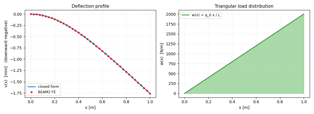
Plot the deflection profile against the closed form#
def v_closed_form(x: float) -> float:
    """Closed-form deflection.

    Integrate :math:`E I\\,v'' = M(x)` twice with
    :math:`v(0) = v'(0) = 0`.  After algebra,

    .. math::
        E I\\,v(x)
        = -\\frac{q_{0}}{120 L}\\, x^{2}\\,(20 L^{3} - 10 L^{2} x + x^{3}).
    """
    return -q_0 * x**2 * (20.0 * L**3 - 10.0 * L**2 * x + x**3) / (120.0 * L * EI)


fe_uy = np.array([_node_dof(int(i + 1), 1) for i in range(N_ELEM + 1)])

import matplotlib.pyplot as plt  # noqa: E402

fig, (ax1, ax2) = plt.subplots(1, 2, figsize=(11.0, 4.0))

xs_dense = np.linspace(0.0, L, 401)
ax1.plot(
    xs_dense,
    [v_closed_form(x) * 1e3 for x in xs_dense],
    "-",
    color="#1f77b4",
    lw=2.0,
    label="closed form",
)
ax1.plot(xs, fe_uy * 1e3, "o", color="#d62728", markersize=4, label="BEAM2 FE")
ax1.set_xlabel("x [m]")
ax1.set_ylabel("v(x)  [mm]   (downward negative)")
ax1.set_title("Deflection profile", fontsize=11)
ax1.legend(loc="lower left", fontsize=9)
ax1.grid(True, ls=":", alpha=0.5)

# Show the load distribution alongside.
ax2.fill_between(xs_dense, 0.0, q_0 * xs_dense / L, alpha=0.4, color="#2ca02c")
ax2.plot(xs_dense, q_0 * xs_dense / L, color="#2ca02c", lw=2.0, label="w(x) = q_0 x / L")
ax2.set_xlabel("x [m]")
ax2.set_ylabel("w(x)  [N/m]")
ax2.set_title("Triangular load distribution", fontsize=11)
ax2.legend(loc="upper left", fontsize=9)
ax2.grid(True, ls=":", alpha=0.5)
fig.tight_layout()
fig.show()
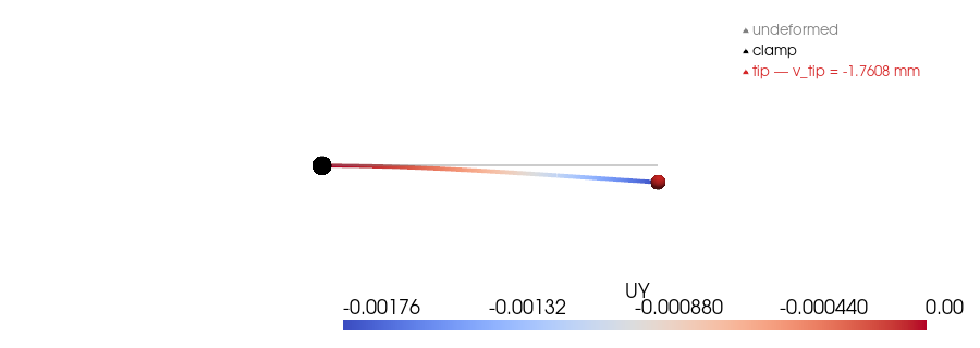
Render the deformed beam#
g = m.grid.copy()
disp_xyz = np.zeros((g.n_points, 3))
for ni in range(g.n_points):
    disp_xyz[ni, 1] = _node_dof(int(ni + 1), 1)
g.point_data["displacement"] = disp_xyz
g.point_data["UY"] = disp_xyz[:, 1]

scale = 1.0 / max(abs(v_tip_fe), 1e-12) * 0.05
warped = g.copy()
warped.points = np.asarray(g.points) + scale * disp_xyz

plotter = pv.Plotter(off_screen=True, window_size=(900, 320))
plotter.add_mesh(g, color="grey", opacity=0.4, line_width=2, label="undeformed")
plotter.add_mesh(warped, scalars="UY", cmap="coolwarm", line_width=4)
plotter.add_points(
    np.array([[0.0, 0.0, 0.0]]),
    render_points_as_spheres=True,
    point_size=18,
    color="black",
    label="clamp",
)
plotter.add_points(
    np.array([[L, scale * v_tip_fe, 0.0]]),
    render_points_as_spheres=True,
    point_size=14,
    color="#d62728",
    label=f"tip — v_tip = {v_tip_fe * 1e3:.4f} mm",
)
plotter.view_xy()
plotter.add_legend()
plotter.show()
Take-aways#
print()
print("Take-aways:")
print(f"  • v_tip within {abs(err_v):.4f} % of -11 q_0 L⁴ / (120 E I).")
print(f"  • |theta_tip| within {abs(err_theta):.4f} % of q_0 L³ / (8 E I).")
print(
    f"  • Same total load Q spread uniformly deflects the tip by only "
    f"{abs(delta_tip_udl / delta_tip_pub):.3f}× the triangular case — "
    "moment-arm matters more than total load magnitude on a slender cantilever."
)
Take-aways:
  • v_tip within 0.0474 % of -11 q_0 L⁴ / (120 E I).
  • |theta_tip| within 0.0625 % of q_0 L³ / (8 E I).
  • Same total load Q spread uniformly deflects the tip by only 0.682× the triangular case — moment-arm matters more than total load magnitude on a slender cantilever.
Total running time of the script: (0 minutes 0.378 seconds)