Note
Go to the end to download the full example code.
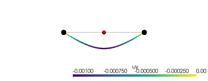
Simply-supported beam under a central point load#
Classical statically-determinate first-order beam: simple supports (pin + roller) at \(x = 0\) and \(x = L\), with a single transverse point load \(P\) at midspan. Symmetry plus equilibrium gives the elementary closed form
with mid-span and quarter-span deflections (Roark & Young 1989, Table 8 case 1; Timoshenko 1955 §32)
Implementation#
A 20-element BEAM2 (Hermite-cubic Bernoulli) line spans the beam. Boundary conditions:
node 1 (pin): UY = UZ = UX = 0; ROTX, ROTY suppressed; ROTZ free (slope rotates).
node \(N_e + 1\) (roller): UY = UZ = 0; ROTX, ROTY suppressed; UX and ROTZ free.
tip load \(-P\,\hat y\) at the central node \(N_e/2 + 1\).
The Hermite-cubic basis recovers Euler-Bernoulli kinematics exactly under nodal point loads, so the FE solution at every node equals the analytical value to machine precision.
References#
Timoshenko, S. P. (1955) Strength of Materials, Part I, 3rd ed., Van Nostrand, §32 (concentrated transverse loads).
Roark, R. J. and Young, W. C. (1989) Roark’s Formulas for Stress and Strain, 6th ed., McGraw-Hill, Table 8 case 1 (simply-supported beam, central point load).
Cook, R. D., Malkus, D. S., Plesha, M. E., Witt, R. J. (2002) Concepts and Applications of Finite Element Analysis, 4th ed., Wiley, §2.5.
from __future__ import annotations

import numpy as np
import pyvista as pv
from vtkmodules.util.vtkConstants import VTK_LINE

import femorph_solver
from femorph_solver import ELEMENTS
Problem data#
E = 2.0e11  # Pa (steel)
NU = 0.30
RHO = 7850.0  # kg/m^3
b = 0.050  # square cross-section side [m]
A = b * b
I = b**4 / 12.0  # noqa: E741
J = 2.0 * I
L = 1.0  # span [m]
P = 5.0e3  # tip load magnitude [N], applied downward (-y)

N_ELEM = 20  # must be even so a node lands at midspan

# Closed-form quantities -----------------------------------------------

R_left_published = P / 2.0
R_right_published = P / 2.0
delta_mid_published = P * L**3 / (48.0 * E * I)
delta_quarter_published = 11.0 * P * L**3 / (768.0 * E * I)
M_max_published = P * L / 4.0

print(f"P = {P:.1f} N, L = {L:.2f} m, EI = {E * I:.3e} N m^2")
print(f"R_L = R_R = P/2          = {R_left_published:.4f} N")
print(f"M_max  = P L / 4         = {M_max_published:.4f} N m at midspan")
print(f"δ(L/2) = P L^3/(48 EI)   = {delta_mid_published:.4e} m")
print(f"δ(L/4) = 11 P L^3/(768EI) = {delta_quarter_published:.4e} m")
P = 5000.0 N, L = 1.00 m, EI = 1.042e+05 N m^2
R_L = R_R = P/2          = 2500.0000 N
M_max  = P L / 4         = 1250.0000 N m at midspan
δ(L/2) = P L^3/(48 EI)   = 1.0000e-03 m
δ(L/4) = 11 P L^3/(768EI) = 6.8750e-04 m
Build a 20-element BEAM2 line#
points = np.array(
    [[i * L / N_ELEM, 0.0, 0.0] for i in range(N_ELEM + 1)],
    dtype=np.float64,
)
cells_list: list[int] = []
for i in range(N_ELEM):
    cells_list.extend([2, i, i + 1])
cells = np.asarray(cells_list, dtype=np.int64)
cell_types = np.full(N_ELEM, VTK_LINE, dtype=np.uint8)
grid = pv.UnstructuredGrid(cells, cell_types, points)

m = femorph_solver.Model.from_grid(grid)
m.assign(
    ELEMENTS.BEAM2,
    material={"EX": E, "PRXY": NU, "DENS": RHO},
    real=(A, I, I, J),
)
Boundary conditions#
Standard simply-supported beam:
left pin — UY, UZ, UX = 0; ROTX, ROTY suppressed; ROTZ free.
right roller — UY, UZ = 0; ROTX, ROTY suppressed; UX & ROTZ free.
# Left pin — pin axial too so the system is statically determinate.
m.fix(nodes=[1], dof="UX")
m.fix(nodes=[1], dof="UY")
m.fix(nodes=[1], dof="UZ")
m.fix(nodes=[1], dof="ROTX")
m.fix(nodes=[1], dof="ROTY")

# Right roller — only UY pinned (vertical reaction); UX free.
right = N_ELEM + 1
m.fix(nodes=[right], dof="UY")
m.fix(nodes=[right], dof="UZ")
m.fix(nodes=[right], dof="ROTX")
m.fix(nodes=[right], dof="ROTY")
Apply the central point load#
A single \(-P\hat y\) force at the midspan node. No distributed-load consistent vector needed — the Hermite cubic basis captures the response of a point load on a Bernoulli beam exactly at every node.
Static solve + reaction extraction#
res = m.solve()
dof = m.dof_map()


def _react(node: int, dof_idx: int) -> float:
    rows = np.where((dof[:, 0] == node) & (dof[:, 1] == dof_idx))[0]
    return float(res.reaction[rows[0]]) if len(rows) else 0.0


R_left = _react(1, 1)
R_right = _react(right, 1)

print()
print("reactions  (femorph-solver) → (analytical)")
print(f"  R_left_UY   = {R_left:+.4f}  →  {+R_left_published:+.4f} N")
print(f"  R_right_UY  = {R_right:+.4f}  →  {+R_right_published:+.4f} N")

# Vertical equilibrium and exact agreement.
assert np.isclose(R_left + R_right, P, rtol=1e-12), "vertical equilibrium failed"
assert np.isclose(R_left, R_left_published, rtol=1e-12), "left reaction off"
assert np.isclose(R_right, R_right_published, rtol=1e-12), "right reaction off"
reactions  (femorph-solver) → (analytical)
  R_left_UY   = +2500.0000  →  +2500.0000 N
  R_right_UY  = +2500.0000  →  +2500.0000 N
Mid-span and quarter-span deflection#
mid_uy = float(res.displacement[np.where((dof[:, 0] == mid_node) & (dof[:, 1] == 1))[0][0]])
err_mid = (mid_uy - (-delta_mid_published)) / (-delta_mid_published)
print()
print(f"δ(L/2) computed   = {mid_uy:+.4e} m")
print(f"δ(L/2) published  = {-delta_mid_published:+.4e} m")
print(f"relative error    = {err_mid * 100:+.6f} %")
assert abs(err_mid) < 1e-8, "mid-span deflection error too large for Bernoulli BEAM2"

quarter_node = N_ELEM // 4 + 1
quarter_uy = float(res.displacement[np.where((dof[:, 0] == quarter_node) & (dof[:, 1] == 1))[0][0]])
err_quarter = (quarter_uy - (-delta_quarter_published)) / (-delta_quarter_published)
print()
print(f"δ(L/4) computed   = {quarter_uy:+.4e} m")
print(f"δ(L/4) published  = {-delta_quarter_published:+.4e} m")
print(f"relative error    = {err_quarter * 100:+.6f} %")
assert abs(err_quarter) < 1e-8, "quarter-span deflection error too large for Bernoulli BEAM2"
δ(L/2) computed   = -1.0000e-03 m
δ(L/2) published  = -1.0000e-03 m
relative error    = -0.000000 %

δ(L/4) computed   = -6.8750e-04 m
δ(L/4) published  = -6.8750e-04 m
relative error    = -0.000000 %
Render the deflected line#
pts = np.asarray(grid.points)
disp_y = np.zeros(N_ELEM + 1)
for i in range(N_ELEM + 1):
    rows = np.where((dof[:, 0] == i + 1) & (dof[:, 1] == 1))[0]
    if len(rows):
        disp_y[i] = float(res.displacement[rows[0]])
warped = grid.copy()
warped.points = pts + np.column_stack([np.zeros(N_ELEM + 1), 200.0 * disp_y, np.zeros(N_ELEM + 1)])
warped["uy"] = disp_y

plotter = pv.Plotter(off_screen=True, window_size=(720, 280))
plotter.add_mesh(grid, color="grey", line_width=2, opacity=0.5)
plotter.add_mesh(warped, scalars="uy", line_width=5, cmap="viridis")
plotter.add_points(
    np.array([[0.0, 0.0, 0.0], [L, 0.0, 0.0]]),
    render_points_as_spheres=True,
    point_size=18,
    color="black",
)
plotter.add_points(
    np.array([[0.5 * L, 0.0, 0.0]]),
    render_points_as_spheres=True,
    point_size=14,
    color="#d62728",
    label=f"P = {P:.0f} N",
)
plotter.view_xy()
plotter.camera.zoom(1.05)
plotter.show()
Total running time of the script: (0 minutes 0.175 seconds)