Note
Go to the end to download the full example code.
Cantilever beam under a tip moment#
Pure-bending end-loaded prismatic beam, the simplest test of moment-driven Bernoulli kinematics. A clamped-free cantilever of length \(L\) carries a moment \(M_0\) about the out-of-plane axis applied at its tip; equilibrium and elementary integration give a closed form (Roark & Young 1989, Table 8 case 4; Timoshenko 1955 §32):
so the slope and tip rotation / deflection are
and the curvature \(\kappa = M_0 / (E I)\) is constant along the entire span — a cantilever under pure end moment deforms into a circular arc of radius \(E I / M_0\).
Implementation#
A 10-element BEAM2 (Hermite-cubic Bernoulli) line spans the beam. Boundary conditions: clamp all 6 DOFs at the root. Loading: a single \(+M_z\) moment at the tip node.
Hermite cubic shape functions interpolate displacement and slope simultaneously, so the FE response under a pure tip moment matches the analytic parabolic deflection profile to machine precision at every node.
References#
Timoshenko, S. P. (1955) Strength of Materials, Part I, 3rd ed., Van Nostrand, §32.
Roark, R. J. and Young, W. C. (1989) Roark’s Formulas for Stress and Strain, 6th ed., McGraw-Hill, Table 8 case 4 (cantilever, end moment).
Cook, R. D., Malkus, D. S., Plesha, M. E., Witt, R. J. (2002) Concepts and Applications of Finite Element Analysis, 4th ed., Wiley, §2.5 (Hermite cubic shape functions).
from __future__ import annotations

import numpy as np
import pyvista as pv
from vtkmodules.util.vtkConstants import VTK_LINE

import femorph_solver
from femorph_solver import ELEMENTS
Problem data#
E = 2.0e11  # Pa (steel)
NU = 0.30
RHO = 7850.0  # kg/m^3
b = 0.050  # square cross-section side [m]
A = b * b
I = b**4 / 12.0  # noqa: E741
J = 2.0 * I
L = 1.0  # span [m]
M0 = 1.0e3  # tip moment [N m] about +z

N_ELEM = 10  # 10 segments → exact at every node for Bernoulli kinematics

# Closed-form quantities -----------------------------------------------

theta_tip_published = M0 * L / (E * I)
v_tip_published = M0 * L**2 / (2.0 * E * I)
kappa_published = M0 / (E * I)
R_arc = 1.0 / kappa_published  # radius of the deformed arc

print(f"M0 = {M0:.1f} N m, L = {L:.2f} m, EI = {E * I:.3e} N m^2")
print(f"θ_tip = M L / (E I)        = {theta_tip_published:.6e} rad")
print(f"v_tip = M L^2 / (2 E I)    = {v_tip_published:.6e} m")
print(f"κ     = M / (E I)          = {kappa_published:.6e} 1/m  (constant)")
print(f"R_arc = E I / M            = {R_arc:.4f} m  (radius of deformed arc)")
M0 = 1000.0 N m, L = 1.00 m, EI = 1.042e+05 N m^2
θ_tip = M L / (E I)        = 9.600000e-03 rad
v_tip = M L^2 / (2 E I)    = 4.800000e-03 m
κ     = M / (E I)          = 9.600000e-03 1/m  (constant)
R_arc = E I / M            = 104.1667 m  (radius of deformed arc)
Build a 10-element BEAM2 line clamped at x=0#
points = np.array(
    [[i * L / N_ELEM, 0.0, 0.0] for i in range(N_ELEM + 1)],
    dtype=np.float64,
)
cells_list: list[int] = []
for i in range(N_ELEM):
    cells_list.extend([2, i, i + 1])
cells = np.asarray(cells_list, dtype=np.int64)
cell_types = np.full(N_ELEM, VTK_LINE, dtype=np.uint8)
grid = pv.UnstructuredGrid(cells, cell_types, points)

m = femorph_solver.Model.from_grid(grid)
m.assign(
    ELEMENTS.BEAM2,
    material={"EX": E, "PRXY": NU, "DENS": RHO},
    real=(A, I, I, J),
)

m.fix(nodes=[1], dof="ALL")  # full clamp at root
m.apply_force(N_ELEM + 1, mz=M0)  # tip moment about +z
Static solve + extract tip rotation / deflection#
res = m.solve()
dof = m.dof_map()
tip_uy_idx = np.where((dof[:, 0] == N_ELEM + 1) & (dof[:, 1] == 1))[0][0]
tip_rotz_idx = np.where((dof[:, 0] == N_ELEM + 1) & (dof[:, 1] == 5))[0][0]
v_tip = float(res.displacement[tip_uy_idx])
theta_tip = float(res.displacement[tip_rotz_idx])

err_v = (v_tip - v_tip_published) / v_tip_published
err_th = (theta_tip - theta_tip_published) / theta_tip_published

print()
print("tip response  (femorph-solver) → (analytical)")
print(f"  v_tip      = {v_tip:+.6e}  →  {v_tip_published:+.6e}  ({err_v * 100:+.6f}%)")
print(f"  θ_tip      = {theta_tip:+.6e}  →  {theta_tip_published:+.6e}  ({err_th * 100:+.6f}%)")

assert abs(err_v) < 1e-8, f"tip deflection error {err_v:.2e} too large for Bernoulli BEAM2"
assert abs(err_th) < 1e-8, f"tip rotation error {err_th:.2e} too large for Bernoulli BEAM2"
tip response  (femorph-solver) → (analytical)
  v_tip      = +4.800000e-03  →  +4.800000e-03  (-0.000000%)
  θ_tip      = +9.600000e-03  →  +9.600000e-03  (-0.000000%)
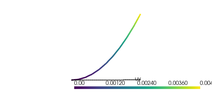
Verify the parabolic deflection profile#
Every node should satisfy \(v(x) = M_0 x^2 / (2 E I)\) to machine precision.
x_nodes = points[:, 0]
v_published_profile = M0 * x_nodes**2 / (2.0 * E * I)
v_computed_profile = np.zeros(N_ELEM + 1)
for i in range(N_ELEM + 1):
    rows = np.where((dof[:, 0] == i + 1) & (dof[:, 1] == 1))[0]
    v_computed_profile[i] = float(res.displacement[rows[0]])
np.testing.assert_allclose(v_computed_profile, v_published_profile, atol=1e-14, rtol=1e-10)
print()
print("OK — full deflection profile v(x) = M_0 x^2 / (2 E I) matches at every node.")
OK — full deflection profile v(x) = M_0 x^2 / (2 E I) matches at every node.
Verify constant curvature κ = M / (EI)#
A second central difference on the slope \(\theta_z(x)\) at every interior node should recover the constant \(\kappa = M_0 / (E I)\) to within the Bernoulli-FE-at-node precision floor.
theta_profile = np.zeros(N_ELEM + 1)
for i in range(N_ELEM + 1):
    rows = np.where((dof[:, 0] == i + 1) & (dof[:, 1] == 5))[0]
    theta_profile[i] = float(res.displacement[rows[0]])
kappa_estimates = np.diff(theta_profile) / np.diff(x_nodes)
print(
    f"κ estimates (per element): mean = {kappa_estimates.mean():.6e}, "
    f"std = {kappa_estimates.std():.2e}"
)
np.testing.assert_allclose(kappa_estimates, kappa_published, rtol=1e-10)
print(f"OK — κ uniformly equals M_0/(E I) = {kappa_published:.6e} 1/m within 1e-10.")
κ estimates (per element): mean = 9.600000e-03, std = 6.48e-16
OK — κ uniformly equals M_0/(E I) = 9.600000e-03 1/m within 1e-10.
Render the deflected line + reference circular arc#
x_dense = np.linspace(0, L, 200)
v_dense = M0 * x_dense**2 / (2.0 * E * I)
arc_pts = np.column_stack([x_dense, v_dense, np.zeros_like(x_dense)])
arc = pv.PolyData(arc_pts)

warp = grid.copy()
warp.points = grid.points + np.column_stack(
    [np.zeros(N_ELEM + 1), 200.0 * v_computed_profile, np.zeros(N_ELEM + 1)]
)
warp["uy"] = v_computed_profile

plotter = pv.Plotter(off_screen=True, window_size=(720, 320))
plotter.add_mesh(grid, color="grey", opacity=0.3, line_width=2)
plotter.add_mesh(
    arc,
    style="points",
    color="black",
    opacity=0.4,
    point_size=3,
    label="closed form v(x)",
)
plotter.add_mesh(warp, scalars="uy", line_width=5, cmap="viridis")
plotter.view_xy()
plotter.camera.zoom(1.05)
plotter.show()
Total running time of the script: (0 minutes 0.159 seconds)